A few simple steps are essential that you can adopt to optimize your designs. We do optimization for computer numerical control (CNC) machining. You can get extra out of CNC machining broad capabilities. You have to follow the DFM (design for manufacturing) rules. Yet, it is not a piece of cake and can be difficult. As there are no exact industry standards are available.
In this article, I will write a comprehensive guide to the top design practices for CNC machining. CNC machining includes different operations. To make the top plate logo cover, there is a need for CNC machines. I studied various Chinese companies to collect this appropriate data.
The main restrictions in the way of CNC design:
CNC offers excellent design flexibility, but there are some limitations. These boundaries relate to the basic mechanics of the cutting process. Moreover, these limitations concern tool to access and tool geometry.
Tool geometry:
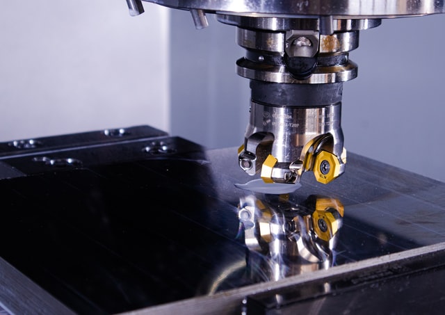
The largest general CNC cutting tools (including end mill tools and drills) have;
- A cylindrical shape
- And a limited cutting length
As the material is removed from the component, the following process will start. And there will be a transfer of geometry of the tool to the machining part. The inner corners of the CNC component always have a radius. It does not matter how small the cutting tool we are using.
Tool access:
The cutting tool reaches the workpiece from the top to remove the material. Features that are not accessible are different. We cannot perform the CNC machining process on these features. The one exception to this rule is available when it comes to undercuts. And try to create a separate section on undercuts. Good design practice is to align all the features of your model, such as;
- Cavities
- Holes
- Vertical walls, etc
Yet, see this principle as a recommendation, not a restriction. As the 5-axis CNC machining systems offer state-of-the-art workpiece capabilities. Tool access is also a problem while machining features with a vast depth-to-width ratio.
It would be best to have tools with extended lengths to approach the bottom of a deep cavity. The meaning of this is a wide choice of motion for the end effect. And it increases the chirping of the machine and reduces the achievable accuracy.
It will make production easier if you design parts in a good way. The tools with the possible minor diameter and shortest length will help.
Guidelines for CNC design:
Often a challenge arises in designing CNC machining parts. That is, there is no set standard for the whole industry. But some factories are following CNC’s international standards. The same industries you will often see working in China. Xiamen Prime Kunwu Technology Co., Ltd. is one of the best CNC services providers.
CNC machine and tool manufacturers are improving technology capabilities on regular basis. They are doing their best to stay within their limits. I am going to describe some common features in detail.
-
Pockets and cavities:
The recommended depth of the cavity: is four times the cavity depth
End mill tools generally have a restricted cutting length. And that cutting length is approximately 3 to 4 times their diameter. Tool deflection, vibrations, and chip evacuation will become more prominent. And that will happen when cavities have a minor depth-to-width ratio.
To get good results, restrict the depth of the cavity to 4 times its width. But the idea will be changed if there is a need for more considerable depths. So, make the design of the parts with a variable cavity depth. When it comes to deep cavity milling, that will be different. The cavities that have depths greater than 6 times the tool diameter fall in this. And we name them deep milling cavities.
-
Internal edges:
For better understating, in this section, I will go deeper;
a) Vertical corner radius:
The recommendation in this regard: 1/3 times cavity depth (or bigger)
The recommended value for the inner corner radius ensures a lot. We can use a tool of suitable diameter in this process. Moreover, it conforms to guidelines for the depth of the proposed cavity.
The result will differ if we increase the corner radii a little beyond the suggested value. And the increase (e.g., by 1 mm) permits the tool to cut a circular path instead of a 90 angle. Always prefer it because it results in a better quality surface finish. For sharp 90-degree internal corners, I will recommend something different. Try to consider a T-bone undercut instead of minimizing the corner radius.
b) Floor radius:
The recommendation in this regard: no radius, 0.5 mm, or 1 mm, Workable: many radiuses
End mill cutting tools have flat or little rounded lower cutting edges. With the use of a ball and tools, the machining is possible on other floor radii. It is excellent design practice to use the suggested values. And the main reason is that mechanics prefer it over the rest.
-
Thin walls:
The recommendations in this regard: 1.5 mm (plastics), 0.8 mm (metals), Workable: 0.5 mm (metals), 1.0 mm (plastics)
Reducing the wall thickness decreases the hardness of the material. It increases vibration during CNC machining and reduces achievable accuracy. Plastics are at risk of warping and softening. The reasons are an increase in temperature and residual pressure. Always examine the applicable values mentioned above on a case-by-case basis.
Final Words:
I am sure that the procedure to design parts for CNC machining is at your fingertips now. Every single detail is mentioned in an easy way for better understanding. But if you have any queries about design or CNC machining. You can give your feedback via comment.


